Thursday, June 16, 2016

Dash It All! Another Setback!

Well, it has been over two years since I updated the bally site. What can I say? Life sometimes deals one a rum hand, what.

Opportunities to show off the old Aetheric Neuralizer have become rather less of late, with the collapse of not one but two local "cons", and consequently one has not felt the drive to work on the outstanding issues overmuch. I am still doing concept drawings for the Moran Radium-Enhanced Sidearm, but haven't managed to get the aesthetics exactly right yet. I know how I'm going to get it all to work, I'm just not happy with the look of the bally thing yet, and so cannot get cracking.

There was another setback with the improved barrel mechanism of the Aetheric Neuralizer too. After several weeks of messing about with EL-Wire and programmable sequencers I came to the conclusion that construction and aesthetics were finalised but that the technology simply wasn't up to snuff.

I wanted the Aetheric Neuralizer to feature a helix of green light, slowly "screwing out" along the barrel at perhaps two revolutions per second. When the first trigger is pulled, I wanted the rate of revolutions to slowly increase to a crescendo of whirling threat display, the better to convey to the targets the peril in which they would be standing.

Much expense and thrashing about with electrons was done at the Moran Advanced Aetheric Physics Laboratory, only to end up concluding that the bally EL Wire upon which the effect was to be based is not luminous enough to do the job when placed next to the magnificent radiance of the linear resonator, the centre-piece of the Aetheric Neuralizer.

So I am currently researching an alternative using Light Emitting Diodes. I doubt I can achieve the same levels of sheer impressiveness the EL Wire promised while I was in the grip of whatever possessed me to consider it in the first place. The best I've been able to devise so far is a more linear effect, a sort of stroboscopic pulsing. This in turn may dictate a complete re-envisioning of the barrel assembly design.

It might just be better to cut my losses on the Aetheric Neuralizer and use this new effect on a completely different weapon.

Speaking of which, I've been doodling around trying to get to grips with how to best realise the Moran Precision Aetheric Rifle. I'm close, but not very close, to a final design.

This longarm for the modern man - and the more adventurous modern lady I might add - will feature the ultra-secret Moran Enhanced Disc Resonator, and such is the effectiveness of this device that it will not require one to lug around a Moran Aethero-Galvanic Exciter to make the bally rifle work either.

This alone will make the longarm more portable and more attractive to the fairer sex, who find it difficult to add a Moran Aethero-Galvanic Exciter to their already busy collection of handbags and whatnot, and who seeming cannot overcome the urge to attempt to store powder compacts in the case, often to disastrous effect.

It has also been noted by such luminaries as the solicitors in charge of the estate of the late Lord Kelper that the Aethero-Galvanic Exciter impedes one should the need for sudden and rapid retreat present itself to the hunter-explorer, although they do agree that Moran Laboratories are in no way liable for the late Lord Kelper's demise at the feet of a Venusian Brontostampus (or more precisely, a stampede of some thirty-four of the legendarily testy beasts), since the user's handbook specifically and clearly states in unambiguous terms that the device has only been tested on Mars and Earth, and that attempts to deploy it elsewhere must be considered experimental in nature and entirely at the wielder's own risk.

And so I close this report in the hope that I will soon be able to report a new era in Aetheric Armaments and Radium Enhanced technology.

Tuesday, March 18, 2014

More Projects To Come

I managed to score a handful of plastic "replica" Broomhandle Mauser airsoft pistols for a ridiculously low cost, so my vision of producing a steampunky Mauser with glowing effects is one phase closer to mildewing in a box in the basement for the next 15 years.

Why the Mauser, you ask?

Well, it has an iconic shape so that even a really naff realization of the weapon is recognizable as what it is supposed to be.

It has plenty of space once the airsoft mechanism is pulled out for batteries and electronic driver circuits.

It has a venerable history as a historical gun modded for futuristic ray-gun needs. Which is to say that Lucas made Han Solo's gun out of one.

And it fits the Victorian Steampunk Era.

So another incoherent build log shall come into being.

Sunday, March 16, 2014

Progress, Of Sorts

I received in the post on Thursday a replacement sequencer board for the EL Wire, and on Saturday night I retired to the lab to test it.

 I used my new variable heat soldering iron to close the "solder switch", in reality a pair of closely spaced tracks on the circuit board that you bridge with solder in order to bypass the part of the circuit that steps down the 12 volts of the supply (provided by the Moran Aethero-Galvanic Exciter) to around three volts for the inverter that powers the wire. I was using a 12 volt inverter and so didn't need this feature.

I plugged in the EL Wires I had made, attached the inverter and applied power and was treated to a display of flashing EL Wire in different colors, as expected.

Emboldened by this, I closed the solder switch on the original board (which I had closed with a temporary conductive clamp before) and connected it up and lo and behold, it was working too! My awful repair to the damaged board was holding!

So when I can find time I can move forward with the project to upgrade the Neuralizer's barrel pyrotechnics *and* the backpack of my spacesuit.

Sunday, January 5, 2014

A New Project Is Begun

Work on the Neuralizer upgrade has ceased pending the acquisition of a new EL Wire sequencing board. The last one purchased puffed out Magic Smoke and has proved resistant to my repair skills, and the first needs some reconfiguring and reprogramming to overcome a design flaw that may be dangerous.

But I've finally managed to source a globe from which I can hopefully fashion both a "slipstream" Captain Video-style space helmet and my long-delayed Steampunk Space Helmet.

The first is a matter of cutting a larger hole in the thing and fabricating a neck/chest fitting for it and possibly some side-mounted "earphones" with small aerials.

The latter will require dressing it out in the manner of a diving helmet, a relatively simple task.

A fan will also have to be arranged to defog the "glass" - a lesson some Hollywood FX designers didn't twig in some big-budget films.

I've obtained a globe and will be undertaking some experiments in the near future. Hopefully these will result in a workable design that I can use. I'll try and make a better job of documenting this process than I did with the neuralizer.

Saturday, October 26, 2013

New Technology Brings Fiasco

So what the Dickens happened? I report on exciting new technology deployment possibilities and then...not a dicky-bird for months.

Well, it all started in a very promising manner, with the acquisition of a few yards of Electroluminescent Wire (EL Wire in the vernacular) and a sequencer circuit to make them illuminate in patterns.

The first problem was that the EL Wire terminated in one sort of plug and the sequencer expected a different one. This was a trivial operation.

The second was that I had four two yard strands and I needed eight one yard strands, thus I was forced to become adept at terminating EL Wire (and acquire a few bits and bobs that are not part of the casual electrician's toolkit).

This involves cutting away some of the plastic cladding from the metal core wires, teasing out the two hair-fine "corona wires" without breaking them, winding copper tape around the plastic cladding at the cut-off point, soldering the corona wires to the tape, scraping off the phosphor coat on the protruding center wire and soldering the plug wires to the center wire and the tape. I only had to re-do two of them.

Then I discovered there was a design flaw in the sequencer. It could be worked around, but there was an upgraded circuit so I obtained one of them instead. Then I had to solder in so-called "headers" so the sequencer could be reprogrammed using my portable Babbage machine.

The new board could take 12 volts, which would be convenient for a number of reasons but required a new inverter, which had the wrong plugs and so on and so forth.

Eventually everything was sitting on the bench with the right plugs on the right wires. I connected up the various pieces and was rewarded with some rather strange flickerings that then settled down to the sequence I expected. It was a good start and I was just about to disconnect everything and retire to the living room for some reprogramming of the sequencer when there was a fizz and a puff of smoke and that was that for the sequencer.

It turned out one of the wire tracks on the circuit board had melted.

So, I retired in disgust from the laboratory and haven't gone back inside.

Friday, May 10, 2013

New Technology Brings New Ideas

Well, sort of. I have been experimenting with Electro-Luminescent Wire with a view to replacing the rather disappointing lighting effect inside the Neuralizer's barrel shield, currently a steady green light provided by two four-inch cold cathode lamps, with a more dynamic one in keeping with the lightning effect of the Lumin Disc in the Aethero-Galvanic Exciter and the plasma-snake of the central resonator in the Neuralizer itself.

To do this I obtained an EL Wire sequencer which has proved problematical due to a design issue (in the circuit board). There are work arounds available and I'm following them, but they require reprogramming the board and that is a non trivial operation. In the interim I have also ordered the new version of the sequencer and perhaps that might be the best way to go. We'll see.

The El wire offers a rather nice form factor that can be used in many creative ways, and in conjunction with the programmable sequencer offers some really interesting possibilities such as moving patters of light that change over time or upon performing an action - like pulling the trigger or perhaps adjusting the stopcock on the front end.

In the near term, another upgrade has suggested itself, this time to the Aethero-Galvanic exciter. In the previous article I talked about the need for a three volt supply for the Lumin Disc while at the same time a twelve volt supply was needed for the Neuralizer. I spoke of how I solved this using a separate three volt battery connected to a relay.

Well, I've found a nice little three volt power supply that can be driven from a twelve volt DC source, which makes the separate battery unnecessary. Better yet, it makes the battery optional, and opens up the possibility of using a wide range of different batteries, three volt, nine volt, whatever comes to hand. In theory I can even do away with the relay, which will obviate one source of failure. Not sure that I will, though. That is still under review.

But it does mean that I will be able to use the one twelve volt lead acid battery to run everything, and when that loses charge I can swap in a 9V battery to run just the Lumin Disc. Space will be more efficiently used inside the box and options will be widened.

So that's next up on the agenda.

Sunday, January 20, 2013

An Interlude with Wiring.

Now the real problem with the Neuralizer is that is gobbles electricity. There was no chance that it would ever be practical to make the power supply a self-contained affair, hence the need for the Aethero-Galvanic Exciter (or in more prosaic terms, the battery box).

But it couldn't be just a box, not for something as optically busy as the Neuraliser. It would have to be a piece of optically-active sculpture in its own right, and I'd seen Lumin Discs incorporated into steampunk handbags before, so when I came across a source of inexpensive three-inch diameter Lumin Discs it was obvious what would be the perfect jazzer-upperer for the Aethero-Galvanic Exciter.

The only fly in Nurse McReady's Surgical Bruise Lotion is that the Neuraliser requires a twelve volt supply, whereas the Lumin Disc requires a three volt supply. I could have built something called a voltage divider, but I'm not electronically astute enough to build much beyond a resistor string and though one can turn such things into voltage dividers they waste energy (already in limited supply) and the voltage across the Lumin Disc would fall off as the general voltage dropped, causing G_d knows what sort of behaviour.

The easiest way to address the issue would be to use the twelve volt battery to power the Neuraliser and a separate three volt battery to power the Lumin Disc. Controlling all this through one switch would require a relay.

A relay, for those who have never seen one, is an electromagnet that throws a switch when the coil is energised. The switch can in fact be several switches, so I would use a low-current consumption twelve volt  relay with two "normally open" switches, one to switch the voltage for the Neuraliser, the other to turn on the Lumin Disc.

The connections are as follows: The battery positive is connected to the 2 amp fuse. The fuse is connected to a Y splitter, one leg connected to the rotary switch that masquerades as the red stop tap on the front of the Aethero-Galvanic Exciter, the other to one side of one of the relay switches. The other side of the relay switch is connected to the power socket in the side of the Aethero-Galvanic Exciter, and the other side of the rotary switch is connected to one of the relay coil connectors. The other relay coil connectors is connected to a Y splitter, one leg of which goes to the negative pole of the twelve volt battery and the other to the socket in the side of the Aethero-Galvanic Exciter.

The Lumin Disc is modified by removing the shield covering the circuitry and lengthening the battery wires. A separate battery holder is obtained, and the positive side of the battery holder is connected to the other relay switch contact. The other side of this switch is connected to the positive terminal of the Lumin Disc. The other terminal of the battery holder is connected to the negative terminal of the Lumin Disc.

NOTE: The Lumin Disc is a polarised device - it is crucial to identify the positive and negative sides of the device and to connect them to the proper terminals of the battery to avoid destruction of the electronics. The Neuraliser electronics are also polarised and proper care must be taken to identify the positive slot in the socket and to wire the positive side of the inverters accordingly.

It is a rule of thumb that we put all switches and fuses in the positive side of the circuit, and a matter of necessity that the fuse goes as near to the battery as possible. The Lumin Disc should also be fused, but since the wires, battery and electronics will be relatively safely housed in the box the danger is much less than with the Neuraliser, where the wires can get caught in scenery, opportunities for short circuits are more numerous and even water could get into the equation if it starts raining.

So what happens when you turn the tap on the Aethero-Galvanic Exciter?

The rotary switch supplies power to the coil of the relay, which throws the two switches, which connects the twelve volt supply to the socket and the three volt supply to the Lumin Disc. I've included a kinematic diagram in an attempt to clarfiy things.


So, if you can see the Lumin Disc effect, there is a connection between the twelve volt battery and the socket and enough juice in that bettery to pull in the relay. I'd really like some sort of voltmeter, but instruments that were dirt cheap in my youth are now impossible to find, and even inexpensive analogue meters are very pricey affairs, especially the ultra-desirable moving coil meters.

Wednesday, November 23, 2011

Building the Aethero-Galvanic Exciter Part 1.


Before you attempt to construct a Moran Aetheric Neuralizer for your very own, you will need to construct a power source for it, since you will need a 12 volt DC supply to test each of the components during the construction of it. This post will describe how to build a rather striking one, with a bill of materials including the source I used for those materials, when I could get the websites of the vendors I used to cooperate.


To construct the Moran Aethero-Galvanic Exciter you will need the following materials:

1/2" pine:

4" x 8" (1 off) for the base of the box
4" x 5" (2 off) for the end pieces
5" x 9 3/8" (2 off) for the front and back
5 1/2 " x 9 3/8" (1 off) for the lid

Hinges (2 off)
Hook-type catch (1 off)

I used a Shutter Hinge kit which had all the parts I needed and more, but came with a steep price tag. The linked version is cheaper than the one I bought, but appears to be identical in detail.

5/16" eye-bolt (2 off)
Spring Clip (2 off)

Webbing Belt

I'd like to say there's an off-the-shelf belt that can be used but I had to make one from an unsuitable webbing belt and a make-your-own eyelet kit. Source the belt in an Army Surplus store. Buy two, you'll need another for the Neuralizer.

12 volt, 7 or 8AH lead/acid battery (I used "Battery Supersite" as my vendor and was very satisfied by their service and expeditious treatment of my order, both of which was first-rate. I've used this vendor more than once and never failed to be favourably impressed).

20 gauge hook-up wire, three or more colours

Spade connectors (2 off) for the battery connector.

NEMA L5-15R receptacle (1 off) Home Depot stocks these and I used theirs, but I can't make their d____d website show it to me.

You'll also need a matching plug and you'll need it now so you can size the hole in the case for it. See the comments about the receptacle with regard to Home Depot, which is where I got mine but the blasted website will not cough it up.

12 volt, 60 mA double pole double throw relay (1 off)
AAA battery holder (1 off)
Long stem potentiometer with on-off switch (1 off)
Inline fuseholder.
Two ampere fuse(s).

Lumin Disc, green (1 off)

1/2" copper 90 degree elbow (2 off)
1/2" copper pipe T fitting (1 off)
1/2" copper pipe for joining above (less than 1 inch required for this purpose; extra will be used for Neuralizer construction).
Red sillcock hand wheel (1 off)

You will also need a 12 volt battery charger capable of charging the lead acid battery. I use a car battery charger from this company that has given years of good service.


You will also need a couple of 1/4" hex nuts (1/4 - 20 is a common size), a washer sized to slip over the potentiometer shaft but not to exceed the diameter of the copper T by too much.

I used the following tools, which you will need to have or find equivalents for:

Drill Press - 16mm chuck, 12 speed. (This seems to be a close match to mine, but I've not used it myself)
Table Sander
Palm Sander (Mine's an old Black and Decker. This is the one I'd buy today)
Router Table c/w router (This router is exceptional value for money) My router table was the least expensive Sears model made some 20 years ago and is no longer available, or I'd recommend it.
Biscuit Joiner
30 watt soldering iron

Dremel Tool configured as a router. Can also be used instead of the drill press as a polisher and sander in a pinch.

Sanding drum kit for drill press.

Twist Drill Bits - 1/16th thru 1/2" sizes This set seems properly spiffing. Mine was put together over the years from various sources.
Hole Saw - 2 1/2" diameter
3/4 inch Hole Saw, spade drill bit or Forstner bit

Dial Caliper.

Electrical Solder
Electrician's tape (black and another colour, preferably red)

1/4" Ogee Bit with edge guide
3/8" Rabbet Bit with edge guide
1/4" Straight Bit
1/8" Veining Bit

Clamps big enough to squeeze the box sides together. I use Irwin "quick grip" type but any with a wide-enough throat will do. If you are using clamps with steel jaws use wood shims to avoid dinging up the box. You'll need about six to make the box in one go.

#10 Biscuits

1/4" die matched to the selection of 1/4 inch nuts and die wrench (1/4 - 20 is a common size). The link is to a set that cost a bit, and you'll only need the 1/4" die for this job, but sourcing a separate die is your problem.

Plumbing kit: A blowtorch, solder & flux, brush (plumber's pipe brush - I can't get the website to show it but any hardware store will have one).

And a source of flame.

A small tube of silicone sealant, a bottle of carpenter's yellow glue and a tube of 5-minute epoxy will also be needed.

Construction:

(Refer to the drawing below while following the instructions, and note the cross-section diagram in red of the holes with special profiles).
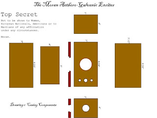

Cut and sand the box panels to size. Cut a biscuit slot in each end of the base and a matching slot on the lower inside face of the end panels to match. Dry fit to ensure the end panels fit properly.

Cut two slots in the long edges of the base and matching slots in the lower inside of the front and back panels and dry fit them to ensure a square and close fit.

Cut slots in the front and back edges of the end panels, and matching slots in the inside face ends of the front and rear panels and dry fit again.

The idea is that every edge-to-face joint will be strengthened by a biscuit, two biscuits where the length is sufficient.

Find the center of the front panel, and drill out a 2.5" hole using a holesaw mounted in a drill press set to rotate at no more than 300 rpm. Go slowly and back the saw out to clear the kerf of sawdust. When you are about 3/4 the way through, reverse the workpiece and continue. This will prevent the circular divot you are cutting from jamming inside the saw.

Using the router (preferably with a router table) and a the ogee bit fitted with a flush edge guide carefully machine the outside edge of the hole to a pleasing profile but do not go too deep. I ended up with a simple round-over rather than a double-curve because I would have had to machine the hole far too deep to get a proper ogee.

Flip the work piece over, switch the ogee bit for a rabbet bit fitted with a flush edge guide and carefully, working slowly remove the material from the back of the hole until you have a circular rabbet just deep enough to flush-fit the lumin disc. It will be a loose fit I'm afraid. I never had the time to refine this part of the construction.

Take the right-hand end panel (the end on the right when you look at the front), find the center and centerpunch. Using a 1 3/8" holesaw, drill out the hole for the receptacle. Fit the electrical socket to the inner side and make a mark or otherwise determine how far in from the outside it sits because you need to widen the hole to accommodate the plug. The dial caliper includes a depth gauge that is useful if you have a drill press with a depth control, but trial-and-error will suffice in a pinch.

The best way to remove the material is to use your drill press and sanding drum kit, sanding in a circular pattern evenly around the entire rim and test fit the plug until the plug fits easily but the gap when the plug is connected is almost too small to see. You'll be removing around 1/16" of material.

Measure the thickness of the right-end end panel and add a 1/2". In the middle of the panel, on the right side, offset by the value you just calculated plus half the diameter of the potentiometer and centerpunch. Drill a 3/4 inch hole.

Assemble the box.

Practice the assembly, which if you've done it properly will be base to ends, then back and front to that sub-assembly. Practice this until you've got it straight. Then do it some more because things will start to go wrong as soon as you begin for real, as we all know.

Apply yellow carpenter's glue to the edges and biscuits and assemble the box and clamp the parts together.

For those without access to a biscuit joiner, one can use a router to cut slots for biscuits but I personally wouldn't advise it unless the builder has much experience with the router. One could also fabricate box-joints or dovetails for the sides and cut a rabbet around the base and a matching slot in each side to accommodate it, but real joinery takes time and skill or jigs that cost as much as the biscuit joiner. I think the best alternative to biscuit joining would be to drill and peg the pieces with dowels, but I will leave that as an exercise for the builder since I already came up with a solution that works well. Simply gluing the joins with no reinforcement will end in tears, fiasco and possible injury.

While the glue is setting up, lets make some plumbing.

You need to assemble the copper elbows and T fitting into a manifold. Study the photographs in the blog and get the general idea of what you are doing. The elbows form a sort of "C" shape and the leg of the T points in the opposite direction. Note that the whole assembly should be flat, with all pipes lying in the same plane. This is important.

Okay, scour the insides of all the fittings with your plumber's brush, and treat the end of a length of pipe with it too. Cut off two small pipe sections with your pipe cutter, enough so the fittings will fit flush together, no longer, apply flux generously and assemble the T to the elbows.

Holding the assembly in a bench vise, heat it until the flame changes colour, then apply solder. It will flow into the microscopic gaps. You don't need gobs of solder to be dripping everywhere, just a smidge is just the ticket. Let this cool before you poke it. It takes a while.

Once cool, you need to drill a 5/16" hole in the bottom of the T fitting. To do this, clamp the manifold in a your drill press vise and run the drill down the axis of the open pipe of the T. This way you can judge the center very easily.

Take the potentiometer and clamp the stem vertically in your bench vise, and carefully fabricate a 1/4 - 20 screw thread on it using your die. Go slowly and back the die off every half turn or so. Make about an inch and a half of thread.

Clip two pieces of red hookup wire, about 3", strip an eighth of an inch of insulation from each end and tin the wire, and the terminals of the switch of the potentiometer (we won't be using the potentiometer winding, we just want the rotary action and the switch). Then solder the wires to the switch terminals.

I never found a truly satisfying way of attaching the potentiometer to the pipe, but I'll share the method I used. Push the potentiometer stem through the hole under the T fitting so it sticks out of the pipe, and fit a quarter inch nut, screwing it down until it sits just above the rim of the T fitting's pipe. Add the washer. There should be not much gap between the washer and pipe, just barely enough to allow it to turn. Add the handwheel. If the fit is too tight, run a 1/4" drill through the hole and try again. Finally screw on a second nut to retain the whole thing and tighten it down.

You should find that the potentiometer is held close to the pipe, but is annoyingly free to turn when you twist the handwheel. Add silicone sealant between the pipe and potentiometer. You must attach the two without impeding the stem rotation or making it obvious from the front. Good luck.

I hate this vehemently. If anyone succeeds in making a more acceptable and visually appealing manifold please post here telling me how you did it with your component sources. Of course, if you can find a source of potentiometers with switches that feature the nut-and-screw-thread mounting you have the option of making a small brass plate to mount the potentiometer to the box front and avoiding the issue.

Once it sets up (hours later) you can use it as a gauge to figure out where you need to drill the half inch holes for the elbows in the front of the box. Drill those holes on the drill press, then relieve the holes with sandpaper until you can slide the manifold/potentiometer assembly into place.

You need now to center the lead acid battery against the rear wall of the box and to fabricate stop blocks to hold it in place in the box. Use offcuts of wood, about 1/2" square. You need one about the length of the battery stuck to the floor of the box and two about two inches long stuck to the back wall. Make the fit snug and use glue, nails and whatever else you think will work to get it all to stick. The battery needs to be removable, but also needs to be secure when the box is in motion on your hip.

With all the holes drilled, sand the box and knock off any sharp corners, then stain it a pleasing colour. I used a medium-dark brown stain. One hint is to seal the box first so the colour is even. I didn't and lived to regret it.

Then you can position the pipe manifold in position and hold it in place - large rubber bands might work best here, and glue it in place using silicone sealant to glue the potentiometer and pipe ends into their respective holes.

I think that is enough for this installment. In the next one we'll do some really nasty electrical work

Please let me know in the comments if this article is unhelpful or can be improved in some specific way. If you have a modification of the design that works particularly well, tell me about that too.

Finally, I have no problem with you taking this design for your own use as a steampunk accessory, but would ask that your finished device be referred to by the name given here. I, Colonel Moran invented the thing, I deserve to be immortalized when you show your stunning oak-with-ivory-inlay version in some national public forum.

Practice your soldering technique before the next article.

Toodle pip!

Thursday, November 3, 2011

Neuralizer Modification

I replaced the "permanent" connection between the Aetheric Neuralizer and the Aethero-Galvanic Exciter with a twist-lock plug and socket combination this evening after work.

After disconnecting the wires and disengaging the silicone rubber I used to anchor them for the showing I used a holesaw to open up the hole in the side of the Aethero-Galvanic Exciter casing to the same size as the round, three pin socket.

Then I had to mill out the hole to make it a little larger for about half its depth to accommodate the plug, which I did with a sanding drum mounted in the drill press.

Mounting the socket so that the plug would orient the way I wanted turned out to be the most awkward job of the entire build. I had to reconfigure the mounting tabs on the socket quite radically, and then the wire mounts were underneath so it had to be wired then installed in the casing, then a wire broke off the switch and had to be re-soldered in-situ, then there was no power in the socket when I twisted the regulator. The list just went on and on.

But eventually the job was done and the Neuralizer can now be separated from its power supply at need. I need to touch up the casing and I think I want to paint the plug. Not sure what color, but the white nylon cord grip that forms the last third of the plug is not appropriate.

Monday, October 31, 2011

The Aethero-Galvanic Exciter

Here we see a composite shot of the Moran Aethero-Galvanic Exciter

It was necessary to cheat a little to properly expose the photograph for both the casing and the resonator window effect. If you were to see the real thing, it would look quite a lot like this when switched on.

Dimension-wise, the casing is around 9 inches in length, 6 inches in height and depth. The device is turned on by twisting the hand-wheel on the plumbing to the right of the picture.

When switched off the plasma effect is turned off and no power is available at the outlet. As it stands the Aetheric Neuralizer is coupled to the device permanently, but a twist-lock socket/plug have been obtained and will be added to the design to enable a more easy transportation of the Neuralizer and the use of the Exciter to power other devices. It will also provide a possible way to recharge the accumulator without de-installing it as is currently required (no pun intended).

I also need to have another go at installing the hinges as the lid is slightly mis-aligned, but that can wait a bit.

Sunday, October 30, 2011

Aetheric Neuralizer In Action

Another picture of the Aetheric Neuralizer being wielded to deadly effect in the hands of the inventor, Colonel Moran.

Note the shoulder-strung Moran Aethero-Galvanic Exciter, another landmark invention from the fertile mind and tireless hands of Colonel Moran.

This device uses the Moran Aetheric Resonator, configured as a disc for this purpose, to provide the electrical energy needed to initiate and control the linear Aetheric Resonator (which can be seen in the picture as the green rod connecting the rear assembly of the Neuraliser with the forward resonator housing), which in turn provides the initiating principle of the Aetheric Neuralizer.

Also visible in this picture is the radiant glow from the Barrel-Mounted Heterodyning Exciters, which indicates that the Aetheric Neuralizer is about to be fired.

Readers should be assured that the device was detuned to a high degree before that took place. No-one was injured in the demonstration of the correct stance and firing technique, and there was no structural damage to the Ravenblood Games emporium.

Aetheric Neuralizer Outing


I took first prize in Ravenblood Games' costume competition tonight largely due to the overwhelming awesomeness of The Moran Aetheric Neuralizer. I'll try and get photos from those who took them.

I have to admit that once I had the Moran Galvanic Exciter figured out I knew I had a winner. You know the concept is working when you want to play with it for fun. I was in real danger of flattening the battery before the event, because I spent so much time watching the effects in action.

The Neuralizer/Power Supply combo drew comment from everyone, as did my fanciful "Praetorian Guard/Space 1889 Soldier" costume. Even though I never fully finished the Neuralizer (I ran out of time and so the external piping and gauges it was supposed to feature were left off) it was still visually stunning.

I'm extremely pleased with myself. I'll add the missing features later and do some internal tidying on both the Moran Galvanic Exciter and the Moran Aetheric Neuralizer - the chocolate-block connectors I used for expedience and screw-up-proofing the circuitry could now be usefully switched out for two-part male/female connectors for example, but it is now a case of super-detailing a product that is basically good to go.

And the host of tonight's event made a point of saying that he would like to display the device in his store, and that was extremely satisfying as a vindication of my design.

Thursday, October 27, 2011

Aetheric Neuralizer XII

Tonight I connected all the wires, re-assembled the various sub-assemblies into a beautiful, metallic weapon of imaginary destruction and connected it to the battery.

I twisted the main hand-wheel and was bathed in the healthy green glow of the Aetheric Resonator, its plasma-trail snaking a brilliant white counterpoint to the background glow.

I spun the forward resonator control regulator hand-wheel and hoisted the Neuralizer into firing position.

I pulled the first trigger and the Lateral Barrel Heterodyning Exciters burst into emerald-coloured life. It was hard to restrain myself but cries of triumph at this stage would have been premature and unseemly, so I limited myself to a smile of satisfaction.

I pulled the second trigger and the entire weapon went dark.

A quick check showed that the half amp fuse had blown. So my decision to go with a huge lead acid battery rather than a few AA cells was well-founded, and I was probably wise to double up that power connecting cable too. I don't know how much juice it is sucking down in "all systems go" mode, but it wants more than half an amp when I press the triggers.

This thing is totally awesome.

And I am awesome for inventing it. I was beginning to doubt that last one.

Wednesday, October 26, 2011

Aetheric Neuralizer XI


Last night the manufactory was a feverish hive of activity as the Neuralizer, now broken down into its component parts, was fitted with sundry components of a mechano-galvanic nature, and the outer casing given a lick of paint (can't go adventuring in the Victorian Era with a handful of PVC) to make it look like brass, which it does, mostly.

This morning I revisited this job with a view to finding some means of preventing everything the Neuralizer touches being coated in super-fine brass dust, which I'm hoping can be summed up as "Testor's Glosscote". I'm keeping the old fingers crossed that the varnish doesn't interact in some vile way with the metallic paint and destroy all this hard work. It wouldn't be the first time paint has mutinied on me.

Also, what I hope is the final construction conundrum was solved when I machined a workmanlike pistol grip for the device from a block of Maple. I sized the grip by eye and used some wood I had left over from another project that was of convenient dimensions. Cutting the top and bottom to a 15 degree angle gave the grip a comfortable rake. Due to a happy error at the table sander due to ham-fistedness, I machined a small front-to-rear taper in the blank which turned out to improve the comfort of the grip considerably.

The breakthrough moment came when I realized that things would be easier to achieve all-round if I mounted the two triggers not side-by-side as originally planned, but one beneath the other so that the lower one could be actuated by the middle finger and the upper by the more traditional index one. This allowed me to use a smaller, sharper router bit to cut a slot down the face of the grip to accept the microswitches, which were then a press-fit. Another pass with a veining bit to provide clearance for the cabling required and I was left wondering why it had taken me so much effort to come up with the solution in the first place.

Attaching it to the rear housing turned out to be easier than I thought it would be too. I simply machined a tapped hole in the rear of the already highly machined piece of wood, aligned with the grips vertical axis, and mounted a length of quarter-inch threaded rod in it and secured the two together with epoxy resin. This enabled me to attach the grip to the housing with a nut. The handle was prevented from twisting by the addition of a short stud just forward of the hole for the threaded rod that protruded into the slot cut for the microswitches/triggers.

This morning I wired those triggers and mounted them in the grip. Nothing wakes one up so quickly as jabbing a hot soldering iron into the left bicep.

A late design change calls for one relay to be re-designated as an optional upgrade, making the rearmost hand-wheel control only the Aetheric Resonator effect rather than forming the first in a cascade of controls for the various effects (which would convey a more realistic firing sequence). I'm nervous about the relay failing, you see. I can live with the actual firing effect not working because of a sub-standard part failure in the field, but the visual impact of the device will largely depend on the plasma effect going on down the spine of the gun and having that go dark because someone tightened the purse strings when it came to making the armature of the relay would be too bad.

Daguerreotypes were taken but are not yet available due to processing delays in the Moran Chemical Imaging Laboratory.

Tonight the device will be reassembled into its working configuration and hopefully I can get on with building the Moran Galvanic Reservoir - a power source of proprietary (and sparkly) design and putting the final touches to the webbing slings.

After I build the Forward Barrel Exciter Shield and attach it in place, of course. The exciter is mounted but needs to be concealed and the light (which is a bit disappointing in the candela department to be honest, but the large and impressive version was simply too long) requires a reflector to properly direct it and hide the rather mundane origin of the green Weird Science glow from public view.

I decided to go with a double length of cabling between the power source and the gun - I'm really too nervous for words when it comes to thin wires people can grab and electricity, even when insulated. I've seen some catastrophes involving current traveling down wires too thin for the flow in my time. A key design element has always been to avoid setting myself on fire while using the Neuralizer. Double cabling introduced a headache with tangling, so I stitched both fabric-clad lengths together with thread.

Should I ever revisit the design, I think I will somehow arrange for hidden bypass switching that can be actuated without stripping down the Neuralizer in the event of a relay failure. I would also like to include an anti-tamper control that disables the whole affair in some non-obvious way.

But other than that, I think the Moran Aetheric Neuralizer is just about ready to be deployed against the Vile Vivisectors of Mars or anyone else who wanders into the line of fire without a white flag and the proper attitude.

Monday, October 24, 2011

Aetheric Neuralizer IXb - Reflections

Once I have the Neuralizer properly assembled and running I shall of course go through and organize these notes into a more workmanlike Bill of Materials and Construction Guide, assuming I can maintain enthusiasm for the job and not collapse in an unmotivatable heap over by the swarf bins.

Thank heavens for the bounty of tea. I don't know how I'd have managed to face the adversity this project has produced without steaming pots of the stuff, applied at regular intervals to the recalcitrant thinking processes.

Anyway. Tonight I expect to make most of the final fittings before the casing is dismantled for cleaning and painting. I shall take photographs if I can spare the time.

Jobs remaining:

  1. Barrel lighting effect and shroud. I believe I have all the materials needed to complete this task, but I may need to obtain some decorative automotive door edging. The brass-finish furnace grill is sharp when cut.
  2. Sound module installation. A very simple job involving double-sided tape and probably gobs of silicone sealant to hold it in place. It's unlikely, but I may use more of that epoxy putty. Depends on the smell/set-up factors involved. Both take forever to set-up but the sealant stinks up the place as it sheds acetic acid during the air curing.
  3. Handle and triggers - this is now most urgent. I still have only the fuzziest internal pictures of what this will look like!
  4. Possible installation of third hand-wheel and switch - this will almost certainly be deferred as an upgrade to be made much later, if at all.
  5. Wiring and test firing. Assuming no malfunctions, this should be the most straightforward of the tasks and should consume no more than a couple of hours at most.
  6. The Battery Box. Time-consuming woodworkery needed here. I'm probably going to double-up the connecting cable, stitching the lengths together with cotton as I have concerns about the current consumption of the Neuralizer when in full "cow the masses" mode. This has been the most disappointing and hard-to-get-convincing part of the build, and I've failed utterly to capture the look I was aiming for.
There are some aesthetic questions still to be answered, but I think mostly this will be good as it stands for the demonstration I have in mind. The aim will be to arrive at Saturday morning in a position to be able to add stuff but not having to do so.

I think I'm happy with most of what's been done. I'm extremely happy with certain aspects of it - the hand-wheel controls are very satisfying in appearance for example, and the Aetheric Resonator is spectacular when power is applied, so much so that it spurred me on when things got unhelpfully hard.

I'm disappointed with my failure to locate a cable of suitably convincing look and behaviour. I wanted something that looked like old-fashioned cable and hung more like rope, in a deep catenary. I'm extremely under-impressed with the quality of the sheet metal screws I was sold by Home Depot, the hexagonal heads of which do not have a consistent profile and offer too-little purchase to a socket spanner. I would advise everyone to avoid these.

The false-starts were relatively few and far between, but have resulted in a small stock of parts deemed not fit for purpose.

These parts, mostly lighting effects that were the wrong size or just not suited to the task at hand rather than non-functional, have been tentatively assigned to the backpack part of a steampunk space-suit project I've been mulling for years. That will feature a convincing steam engine component if I can ever figure it out.

Aetheric Neuralizer IX - Progress (Of Sorts)

Much messing around in the Manufactory Workshop this weekend, not all to good effect.

On Friday a number of parcels finally arrived at the Moran Manufatory's tradesman's entrance which proved to contain the parts necessary to finish the Aetheric Neuralizer. This meant that a number of problems I was still struggling to find an answer to had to be solved "as I went" which never goes well.

Not only that, some parts I had ordered that would form a vital part of both the aesthetic and electrical design turned out to be missing the mounting method I had assumed they would have. The tintype in the supplier's catalogue had been taken from a vantage that did not highlight this design feature, and I cuold not implement the mounting that the parts did come with so I was caught between a Gashant and a Steppe Tiger.

Over the course of the next day and a half I discovered anew that I shouldn't work when tired, especially when drilling large holes in things in which I want a minimum of holes, and that a quarter-inch hole in a PVC pipe fitting can be tapped to accept a 5/16ths threaded stud in a gratifyingly short time. Paint will hide all.

These holes were drilled for two reasons. Firstly, to be threaded so they would accept the eye-bolts for the shoulder-sling, secondly so the stems of the rotary potentiometers c/w on/off switch that will, with the addition of some nice red hand-wheels, place the device firmly in the "steampunk" milieu rather than the "Star Trek" one.

It was these potentiometers that proved so awkward to mount. I had expected them to have the popular large threaded bushing/skimpy nut & crown lock-washer affair so that I could make small brass plates and mount them in those - just as one would with a Marconi Receiver. However, these bally things came with tabs so they could be soldered to a circuit board directly. Useless for the task at hand, as they were too short to wrap around any metal strap large enough to provide a mounting in the tightly curved inner spaces of the Neuralizer's casing.

It was maddening, and I could not come up with a satisfactory solution to the conundrum until late Sunday night, when a combination of double-sided mounting tape and a piece of copper pipe turned out to work rather well.

I manufactured a screw thread onto the stems of the devices first so they would accept a nut, than the hand-wheel then another nut to secure the wheel. Then I applied a generous pad of the tape to the top face of the cylindrical body of the potentiometer and, passing the stem through the hole I had drilled for it in the Neuralizer, pressed it up against the inside of the casing. Then I cut a length of copper pipe that ran from the outer casing surface up to the inner face of the first nut, less a smidgeon.

The result was the pipe was sandwiched lightly between the Neuralizer casing and the inner boss of the handwheel, keeping the whole affair properly seated on the tape and preventing a ding to the handwheel pushing the potentiometer off its rather flimsy mounting.

Naturally, one of the potentiometers would not cooperate and despite these measures came loose and span in its mount so the switch wouldn't work properly. I "solved" this with the aid of some epoxy putty originally intended to allow a tradesman to do shoddy work instead of a proper job. I simply suspended my "must come off again" rule for everything and slathered the bally thing in white paste, which is setting up (still(!)) as I type.

I also secured the inner core of the Moran Aetheric Resonator to the crystal pipe that forms the actuating principle of the Neuralizer. Without this component the Neuralizer is but a tawdry prop suitable only for play-acting.

I was scrupulous when it came to cleaning the crystal tube, and it was only after I had secured the inner core with a special rubber formulation that would ensure an air-tight dust seal that I realized that, what with all the different problems I was solving as I went I had neglected to clean the core itself. Too late by then of course, D_sh It!

The good news is that with the exception of the fabrication of the battery box and the still-vexing matter of how to secure the Superheterodyning Tubes to the barrel, this represents the final problem with the Neuraliser, the rest of the job being a matter of straightforward "x requires y be done" tasks that should take very little effort.

The bad news is that I'm quite behind schedule and must now rush to finish by the debut date.

Thursday, October 20, 2011

Aetheric Neuralizer VIII - Thoughts On Ergonomics

What Ho!

When one looks at the Neuralizer (Aetheric Neuralizer V) one instinctively wants to cradle it in one's upturned palms, tucking the rear assembly into the waist and adopting a sideways stance, but this was not the envisaged method of wielding the device and won't be practical once the handwheels are installed.

I had thought I would use a two-grip approach, similar to a Thompson Submachine Gun, but trials have shown the geometry of the device in firing position doesn't suggest or lend itself to that. This is a shame because I was planning on installing two triggers, one in each grip, to simplify the process of firing - one trigger would activate the barrel light effect, the other the sound.

Getting rid of the forward grip means that the controls must be reconfigured, and I've settled on a double trigger in the rear pistol-grip, set side-by-side with the sound actuating trigger set a little further back than the light actuating one. In this way my index finger can actuate both effects as originally envisaged from the one grip.

This brings up a second vexing issue, namely the need to run two power lines from the rear assembly to the front instead of the one I had planned for. This in turn means using finer gauge wire than I had planned.

Which is moot anyway because the power connecting cord I've settled on has only 20 gauge wire inside it, so unless I run two lengths between the battery box and the Neuralizer and double up the conductor (not desirable), this will burst into flames before any internal wiring melts its insulation off or explodes when it shorts on some metal part or other.

So that's all right then.

It just remains to be decided whether I will attempt to machine the pistol-grip as two halves that sandwich the components, or simply machine the grip core from Maple and clad it with screw-on sides as manufacturers of conventional sidearms do.

And I must also decide how I'm going to attach the grip securely to the Neuralizer. I have a couple of ideas, but none are persuasively convincing. It will be a disaster if the pistol-grip snaps off at the debut.

Toodle pip!

Tuesday, October 18, 2011

Aetheric Neuralizer VII - Sound Practice

What Ho!

Today a new effect was placed on the test bench and given a trial run. Then, once I had recovered my senses, it was placed inside the mock-up of the Neuralizer and given another test run with an audience.

Three hours later my hearing returned. Truly impressive, and absolutely what was needed to give this bally Neuralizer some teeth.

I expect that upon viewing the visual effects at its first outing, some blighter will opine loudly that it's all well and good but hardly impressive, and will goad me into firing it. I will prevaricate of course, finally allowing the smug provocateur to push me into discharging it at them, at which point their respect for the device should become instantly several orders of magnitude higher than at first.

Sadly, I discovered the long-shank potentiometers with integral switch that Iwas planning to use were no longer available for purchase from Radio Shack, or indeed, anywhere on the face of the Earth.

I finally located a viable alternative, but Bad Show, Radio Shack!

Monday, October 17, 2011

Aetheric Neuralizer VI - An Interlude With Electronics

What Ho!

I spent a productive hour or so in the Manufactory experimenting with the electronic core of what will be the Aetheric Resonator, the chief in-weapon effect that will induce awe in the observer (the other being the lumin disk on the battery box).

One of my concerns is that the lead acid accumulator is quite capable of misbehaving in some rather unpleasant ways if care isn't taken and respect for the power it contains not foremost in the inventor's mind. Thus I added a fuse and some proper "spade" terminal connectors to the hook-up.

I had also seen a rather negative review of the very effect I was using, complaining of burns and fire danger. I therefore ran the device for a few minutes to make sure my unit was not as dangerous as that.

All seemed well when I brushed my pinkie finger against the negative battery terminal connection and received what could only be an alternating current shock - from a direct current power supply!

The effect I'm using requires that a DC supply be used, but the science of it requires that a high-voltage AC power source be used. This is achieved by a box of tricks called an inverter.

Given the super-cheapness of the components in the kit, I suspected inadequate design in this unit was feeding back AC onto the power supply lines. Note that I have no advanced electronics training, just what I got in 'A' Level physics 40 years ago. I do however have a box of electronic bits which I doodle with sometimes, and I dipped into that and added a rectifier to the power line.

Problem solved in that touching the battery terminals when the lamp is running does not give me a shock. I have no idea if any other effects are in play, but I will put my voltmeter on the wretched thing once I can remember where it is.

So what needs doing is to add a rectifier to the power connection to the inverter wherever one is used (I'm contemplating another special effect that would require one at the front end of the Aetheric Neuralizer and I do not want to get shocks off the copper rod carrying the negative connection from the rear assembly to the front). Placing it as near to the inverter as possible should prevent shocks - I think that there is danger anywhere between the rectifier and the inverter, if my physics is still good in this day and age.

Aetheric Neuralizer Vb

Bah! I forgot to post the details of how I made those copper rods that separate the front and rear assemblies and reveal the Aetheric Resonator to the eyes of the audience.

Recall that one of the rods must be hollow to allow a power wire (depicted as a red line) to be run through it. That is the lower picture in the diagram below. The two short pieces of threaded rod have been drilled along their axes to form threaded bushings. The copper rod simply rests between the faceplates of the two major structures, held in place by tension provided by the other three rods as depicted in the upper picture of the diagram below.


The outer rods were made by cutting copper pipe to about 9 inches in length and trimming all four to the same size using a table sanding machine.

The three solid rod cores were made from 12.5 inch lengths of half-inch threaded rod, and were attached to their copper sleeves by sliding each one into a copper pipe and nipping it between two nuts, one at each end. The rods were carefully adjusted to get equal lengths of thread at each end before tightening the nuts, and the nuts were only tightened until they fixed the pipe in place in such a way that their flats aligned. This was done by laying the assembly on a flat surface and adusting the nuts until the whole thing didn't rock. Then the nuts were thread-locked using thin-formulation cyanoacrylate adhesive.

Each rod was carefully inserted in one faceplate and fastened using another nut. Attaching the opposite faceplate was an exercise in annoyance as the faceplates are distorted and the rods point inward and so must be gently coaxed into place by springing them outward. The bushings had to be be screwed back until the copper rod could be carefully slid into place and then they had to be turned by hand to extend them and lock the tube into position. It was a trial.

Care also had to be taken to ensure the entire assembly didn't twist, which would produce a corkscrew effect that is unattractive and so not desirable.

And that is how I made the spaceframe rods.

I also polished the copper using a cloth wheel and a special copper abrasive before I assembled the rods, and I applied a coat of Carnuba Wax to them afterward to prevent fingerprints and corrosion.